One of our most important manufactured products used in all industries has many applications & uses. Steel can be molded, pressed, machined, welded & woven to suit different purposes.
Steel making: It’s a three-step process.
Iron Making: Iron ore, coke & a flux (limestone) are combined in a blast furnace to produce molten iron containing about 4% carbon.
Steel Making: Excess carbon is removed in a basic oxygen steel making vessel and the required alloy is added. The molten steel is then cast into billets, blooms, or slabs.
Shaping: Steel is rolled to various sizes and shapes in a rolling mill.
Steels are basically a wide range of iron-based alloys with carbon up to 1 .7 %.
In plain carbon steels other elements are silicon (up to 0.6%), manganese(up to 1.65%), sulphur (up to 0.35%) & phosphorous (up to 0.13%).
1. Elements in Steel:
Carbon
Up to 1.7 %
Promotes formation of carbides (cementite, pearlite & martensite)
Manganese
Deoxidizes the metal and facilitates hot working
Neutralizes sulfur by forming manganese sulfide which increases strength
Provides work-hardening property
Silicon
Deoxidizes steel
Increases resistance to scaling
Phosphorous
An impurity
Decreases ductility and toughness
Sulfur
An impurity
Decreases strength and impact resistance
Improves machinability
2. Types of Steel :
Low Carbon Steels
Carbon up to 0.3 %
Good ductility & weldability
Comparatively low strength & not easily heat treatable
Welding: Have very good weldability.
No special precautions required
Medium Carbon steels
Carbon 0.3 to 0.6 %
Better strength & hardness than low carbon steel
Welding: Slight preheat around 200-250 deg. C and slow cooling.
Use a low hydrogen type electrode
High Carbon Steels
Carbon : 0.6 % to 1.71 %
Easily heat treatable to high hardness
Welding: Poor weldability.
Tendency to crack
High preheat around 300 deg. C and very slow cooling
Maintain high interpass temperature-300 deg. C
Post weld heat treatment and stresses relieving desirable
Alloy Steels
Contain alloying elements other than silicon, manganese, sulfur & phosphorous
High Alloy Steels
Alloying elements more than 10 % ( Ni, Mn, Cr)
Welding: High carbon equivalent hence form martensite.
Preheat around 300 deg. C and maintain interpass
Cool slowly
Low Alloy Steels
Alloying elements less than 10 %
Welding:Preheat requirements minimum.
Types of High Alloy Steels :
Austenitic Manganese steels:
More than 10 % manganese & high carbon
Known as Hadfield Steels
Work harden in service
Welding: Forms hard Carbides at temperatures above 175 deg. C.
No, preheat and fast cooling
Stainless Steels :
Chromium minimum 11.5 %
Excellent corrosion resistance
The addition of nickel gives good toughness & strength at sub-zero and elevated temperatures
Welding: Loose corrosion resistance on exposure over 500 deg. C
No, preheat and fast cooling
Low current & stringer beads
Tool Steels:
Used as Cutting Tools, Shear Blades, Dies, etc.
Contain high carbon
Have a high amount of tungsten, molybdenum, chromium, cobalt, etc., and withstand temperatures up to 550 deg.
Welding: Difficult to weld.
High preheat around 350 deg. C & cool slowly
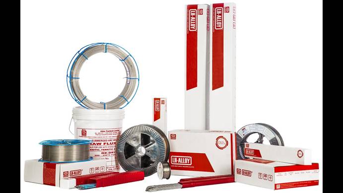
Hence, we at Ador Fontech have designed & developed this exclusive range of LH low heat input welding electrodes, TIG rods & MIG wires to weld all types of steel used in industry, resolving all problems as the unique solution provider for maintenance & repair welding.
To join ferrous with non-ferrous metals, various methods can be adopted.
Mechanical methods: Fasteners, rivets, etc.
Adhesive bonding method: Brazing and Soldering (a.k.a. welding)
Base metal does not fuse: Molten filler gets drawn into close-fit joints through capillary action (surface tension forces).
Brazing filler melts at >450⁰C, soldering at <450⁰C
Welding is the most commonly used process of all.
Welding – A Definition
Welding can be described as a process of joining two or more pieces /edges of metal by producing a localized union through heat (fusion) with or without pressure to create a homogenous joint.
Types of Welding by Metal:
Autogenous: In this process, similar materials are joined without filler wire or electrode Heterogeneous: Process of joining dissimilar materials, using a filler wire or welding electrode
Metal Inert Gas welding or Metal Active Gas welding
SAW – Submerged Arc Welding
2. Solid-State and other Non-electric Fusion Welding: Examples of non-fusion, non-electric process welding are:-
Thermit welding
Ultrasonic welding
Diffusion welding
Deformation welding.
Welding Processes
Fusion welding: Welding in the liquid state with no pressure, Union is by molten metal bridging
Solid State welding: Carried out below the melting point of the metal without filler additions, Pressure is often used,
Union is often by plastic flow.
Solid State welding:
DEFORMATION WELDING: Two Surfaces in contact are brought into very close contact by applying high pressure, which deforms them. E.g., – Forge welding, Roll welding, Extrusion welding. (Not at very high temperatures)
DIFFUSION WELDING: Joining takes place by atomic diffusion of 2 surfaces in contact. Surfaces are usually heated to high temperatures (below the melting point) & pressure may be employed. E.g., Brazing, Braze welding & Soldering. Soldering is an oxy-fuel process of joining metals. The process temperature does not exceed 450⁰. Brazing is also an Oxy-Fuel joining process. The process temperature is between 450⁰ Degrees – 750⁰ degrees. Braze welding is similar to Brazing; the process temperature is above 750⁰ Degrees but below the melting point of the base metal.
Non-Fusion Process: Thermit welding is the most common process used in joining of railway tracks. In this process iron powders and Al binders are kept in Vat or a conical container above the joining rails. When they are fired due to chemical reaction and exothermic reaction, the iron powder melts and forms a joint between rails.
Introduction to Arc Welding: Basic welding processes used in Industry are
MMAW – Manual Metal Arc Welding or Shielded Metal Arc welding
GMAW – Gas Metal Arc Welding/ Flux Cored Arc Welding (MIG, MAG)
GTAW – Gas Tungsten Arc Welding (TIG)
SAW – Submerged Arc Welding
MMAW or SMAW- Shielded Metal Arc process: In the Shielded Metal Arc process or Manual metal Arc welding process the arc is established between Parent Metal and a flux coated welding electrode using electrical energy to melt and deposit weld metal. This is the most commonly used process in the world.
Basic Requirements for the SMAW process:
Heat source: Welding Equipment Current Range 30-400 A –depending on size of the electrode in general, even though there are welding machines used up to 600 Amps AC or DC welding machines can be used in SMAW Operation.
Welding Consumable: Flux coated welding electrode (1.6- 8 mm diameter)
A trained welder is required to operate the process, So SMAW or MMAW is the most commonly used process in the world.
SMAW Process advantages:
This is the simplest of all welding process.
Equipment Portable
Economical Cost of Equipment
Variety of application & wide availability of electrodes
Range of metals & their alloys can be welded
Welding in all Positions
Welding in Indoor & Outdoors
Extended welding cable to long distances in comparison to another process
Limitations of SMAW process:
Low productivity as in a 10-minute cycle welding happens only for 6 minutes
Process also involves a frequent changes of welding electrode
Moisture from flux coatings can create weld-related problems
Safety problems like arc strike, Stray current & electric shock risks
Absolutely Manual process – hence called Manual metal arc welding
GMAW & FCAW processes:
A continuous solid wire, small diameter
GMAW uses solid wire, no flux
FCAW use flux-filled wire
Wire feed through the gun to the arc by wire feeder.
Weld pool may be protected from oxidation by shielding gas.
High productivity 3 kg/h or more
Direct current (DCEP mostly).
Process Requirement:
Welding power source
Wire feeder mechanism- In-built/separate
Gun with gas supply & trigger switch
1. Manual/semi-automatic guns
2. Automatic torches available
3. Can be fitted to automation etc.
Advantages in GMAW:
Faster as compared to TIG & SMAW.
Can produce joints with deep penetration.
Thick & thin, jobs can be welded effectively.
Can be used for fabrication and maintenance repair job.
Can be mechanized easily
Reduced distortion.
Limitation in GMAW:
More Complex due to
Electrode stick-out
Torch angle
Welding parameters
Type and size of electrode
Welding torch manipulation
Not suitable for outdoor welding applications
GTAW or TIG welding: GTAW or Tungsten Inert gas welding uses a consumable Tungsten electrode as the heat source.
This consists of the below. Heat source – welding power source to create an arc between a tungsten tip and the parent metal
30-400A, AC or DC welding machine and 0-20V
Inert gas shielding is used in the process. Consumable: filler rod can be used between 1 to 4mm diameter Process Features:
Excellent control
1. Stable arc at low power (80A at 11V)
2. Independently added filler
3. Ideal for intricate welds eg root runs in the pipe or thin sheet
4. Low productivity 0.5kg/h manual
High quality
1. Clean process, no slag
2. Low oxygen and nitrogen weld metal
3. Defect-free, excellent profile even for single-sided welds
Advantages in GTAW/TIG Process:
No slag inclusion
Clear visibility of arc and job
All position weldability
Suitable for high quality welding of thin material
Root run of thick materials
Ideal for Aluminum, Stainless steel & Titanium
Limitations in GTAW:
Slow as compared to SMAW/MIG/MAG & SAW welding
Possibility of tungsten inclusion in the weld deposit which is hard & brittle
Not suitable for outdoor welding
Submerged Arc welding process (SAW Process): In the Saw Process, as the name signifies, welding happens submerged beneath the flux. SAW process also employs welding consumables usually a wire & arc is established between the welding wire and base metal and welding happens underneath the metal powder of flux, shielding the arc from the atmosphere and its gases.
Heat source: Arc between a wire and base metal Current Range: 200 Amps -1200 Amps
DC operation Power Consumption
35-56 KVA
Power source
Welding head and control box
Welding head travel
Flux recovery system (optional)
Positioners and Fixtures
Hence the basic difference between the two processes is that in the SMAW process, the flux-coated electrode provides the shielding from the atmosphere & in SAW process an external flux is delivered at the arcing area to act as a shield, so welding happens underneath the powder flux fed by a delivery system.
SMAW Process – Advantages:
Simplest of all Arc welding process
Equipment is portable
Economical cost of equipment
Variety of application & wide availability of electrodes
Range of metals & their alloys can be welded
Welding in all Positions
Welding in Indoor & Outdoors
Extended welding cable to long distances when compared to other processes
SAW Process advantages:
High productivity up to 2 to 10 kg per hour
Speed almost up to 2m/ min
Can be easily automated for even higher productivity
Limitations of the SAW process:
Bulky, expensive, and heavy equipment
Flat and horizontal positions only
Thicker sections (6mm and above)
Mostly ferrous materials (also Ni alloys)
Conclusion: A wide variety of processes are available for joining or hard surfacing ferrous and non-ferrous materials. Each of these processes provides different mechanical properties and works in specific conditions, with a welding power source. There are several factors to consider in welding rod selection:
Base metal properties
Tensile strength required
Welding current
Base metal thickness, shape and joint fit-up
Welding position
Specification and service conditions
No. of similar jobs – Scope for automation
Environmental job conditions
These methods are all commonly used by Industry. Before we select any particular method for welding, we need to analyze each of the factors listed above.
ADFL serves the industry with the manufacture and supply of all types of consumables for MMAW, MIG /Mag, TIG, SAW & non-fusion processes like soldering, brazing, and braze welding. This is why Ador Fontech’s name is synonymous with total solutions for any maintenance & repair problem, ensuring the Life Enhancement of Industrial components, to the complete satisfaction of customers.
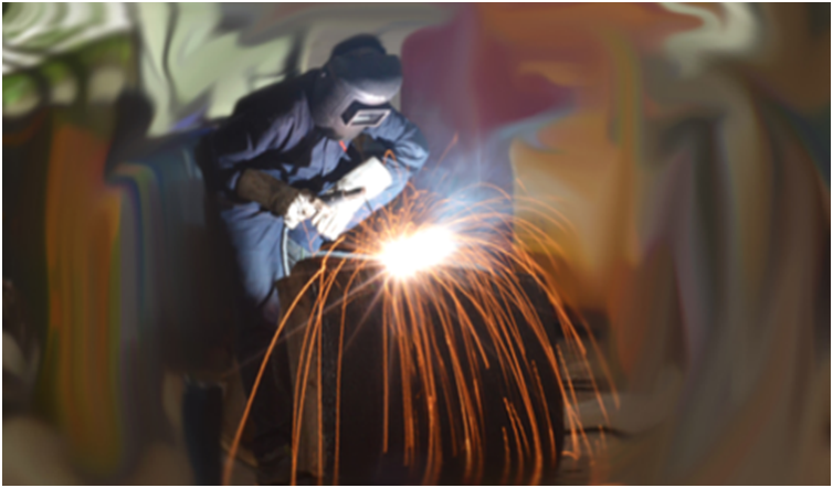
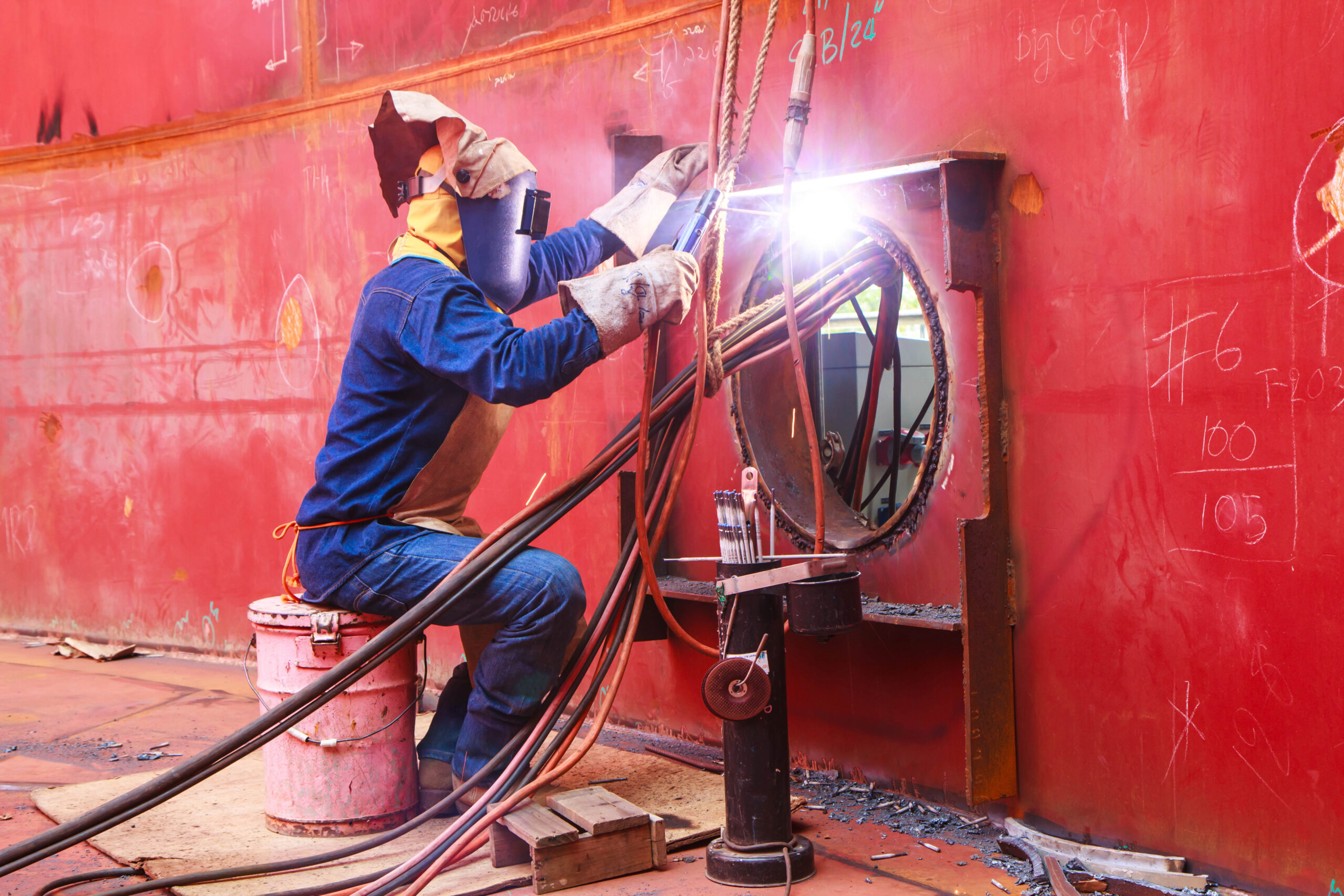
In fabrication, welding helps to join materials using heat to melt the parts together. Useful with metals and thermoplastics, this process typically uses a filler material to the weld pool of molten material, helping to make the joint stronger than the base material. Pressure is used in the process along with heat in welding, while a shield protects the metals from being oxidized in the process.
The most heat sources for joining material using a fusion welding process are listed below:
We have five types of Arc welding Equipment/power sources. These are AC transformer; DC rectifier; AC/DC transformer rectifier, DC generator, and inverter.
MMAW / Arc Welding Equipment – Features
Portable & Versatile equipment
Requires practiced skills
Applicable to a wide range of materials, joints, positions
About 1kg per hour of weld deposited
Properties can be excellent
Benchmark process
MMAW / Arc Welding Equipment – Advantages
This is the simplest of all Arc welding processes.
Equipment is portable
Economical Cost of Equipment
Variety of applications & wide availability of electrodes
The range of metals & their alloys can be welded
Welding in all Positions
Welding can be Indoors or Outdoors
Welding cable can be extended to long distances when compared to other processes
Types of Arc Welding Equipment / Power Sources:
A welding transformer is basically a step-down transformer that brings down the source voltage to weldable voltage. This is simple Arc welding Equipment.
Motor Generator
Motor Generator is also an Arc welding Equipment, which utilizes input power to rotate the generator through an induction motor. This kinetic energy is converted to electrical energy by carbon brushes fitted in the commuter, generating DC current is generated supplying constant power to the process.
In a Diesel Generator, diesel is used as fuel to run the motor to generate electricity; this is widely used in on-site jobs for Arc welding applications
Welding Rectifier
Welding rectifiers are essentially transformers with an electrical device as a rectifier which changes AC to DC. Rectifier basically consists of Silicon diodes, which ensure the flow of current in one direction giving DC output. This is most commonly used with Arc welding equipment.
Welding Inverter
This latest technology power source is the most popular Arc Welding equipment today. A welding inverter is a power block, controlled by software, which offers the required static and dynamic characteristics needed for a specific welding process. It takes AC input and converts it into DC after step-down & then converts it further into high-frequency AC & then again converts it to DC – finally offering a DC output. When using an inverter power source, a user gains all the advantages of thyristor control. Additionally, they get superior efficiency, power savings, better performance, and quality of welding.
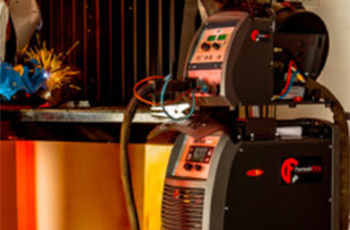
We at Ador Fontech offer the best “Make in India” solutions with Fontech Tornado brand Welding Power sources. We offer both robust Thyristor-controlled machines as well as Power saving Inverter machines for all welding processes like Manual Metal Arc welding, TIG, MIG/MAG, and SAW. Once again, we reiterate our total commitment to total solutions in welding with this range of equipment, catering to the complete requirements of customers.
An Introduction to Shielded Metal Arc Welding (SMAW) process
Heat source
Energy Consumption
An Introduction to Submerged Arc Welding (SAW) process
Advantages with the SMAW Process
Limitations of the SMAW process
Advantages with the SAW Process
Limitations of the SAW process
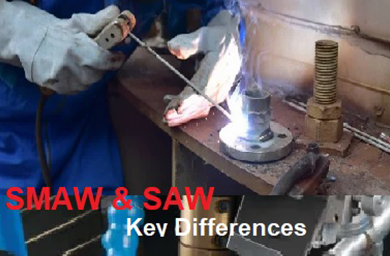
The basic difference between the two processes, SMAW and SAW welding, is this. In the SMAW process, the flux-coated electrode helps to shield the welding process from any interaction with the atmosphere. In the SAW process, an external flux delivered at the arcing area acts as a shield. So, the welding happens underneath the powder flux fed by a delivery system. This is the primary difference between SAW & SMAW processes. Let us get introduced to both processes.
An Introduction to Shielded Metal Arc Welding (SMAW) process
In SMAW or MMAW (Manual Metal Arc Welding), the arc is established between Parent Metal shielded (flux-coated) welding electrodes using electrical energy to deposit weld metal.
Heat source: Arc between metal and a flux-coated electrode (1.6- 8 mm diameter)
Energy Consumption:30 – 400 Amps –depending on the size of the electrode in general, even though there are welding machines that use up to 600 Amps.AC or DC SMAW Operation Power consumption 1-12 KW
An Introduction to Submerged Arc Welding (SAW) process
In the SAW Process, as the name signifies, the welding happens submerged beneath the flux. SAW process also employs a welding consumable, usually a wire. An arc is established between the welding wire and base metal and welding happens underneath the metal powder of flux, which shields the arc from the atmosphere.
Heat source: Arc between a wire and base metal
Current Range: 200 Amps -1200 Amps
DC operation
Power Consumption-35-56 KVA
Power source
Welding head and control box
Welding head travel
Flux recovery system (optional)
Let us take a look at the process advantages & limitations of both SMAW and SAW processes.
Advantages with the SMAW Process:
This is the simplest of all Arc welding processes.
Equipment is portable
Cost of equipment is economical
Variety of applications & wide range of electrodes available
A range of metals & their alloys can be welded
Welding can be done in all positions
Welding can happen indoors & outdoors
Welding cable can be extended to long distances in comparison to the SAW process
Limitations of the SMAW process:
Low productivity as in a 10-minute span, welding happens only for 6 minutes
The process also involves the frequent change of welding electrode
Moisture from flux coatings can create weld-related problems
Safety problems like arc strike, stray current & electric shock risks
Absolutely manual process – hence called Manual Metal Arc Welding
Advantages with the SAW Process:
High productivity up to 2 to 10 kg per hour.
Speed almost up to 2m/min
Can be easily automated for even higher productivity.
Limitations of the SAW process:
Bulky, expensive, and heavy equipment
Flat and horizontal positions only
Thicker sections (6mm and above)
Mostly ferrous materials (also Ni alloys)
Given these essential differences between MMAW/SMAW and SAW processes and their respective advantages and limitations, a considered choice can be made between these processes.
We, at Ador Fontech, offer the best “Make in India” solutions with Fontech Tornado brand welding machines for both SMAW and SAW processes. Once again, we reiterate our commitment to total solutions in welding to the complete satisfaction of customers, with this range of equipment.
Advantages & Disadvantages with Non-fusion welding
Advantages
Disadvantages
Four Requirements of Brazing and Soldering Process
Clean Metal
Filler Rod
Flux
Heat Source
Importance of Controlling Heat in Soldering & brazing
Soldering
Brazing
Soldering and Brazing form a part of non-fusion welding processes, where only the filler rod is melted in the process.
The three common processes used in non-fusion welding are :
Soldering
Brazing
Braze welding
Advantages & Disadvantages with Non-fusion welding
Let’s take a look at the advantages and disadvantages of this type of welding.
Advantages
Lower temperature
Easy assembly
Welds dissimilar metals
Allows disassembly/realignment
Joins metals of different thicknesses
Joins different types of metal
Disadvantages
Results in lower tensile strength
Not an efficient method for thick metal
Not an efficient method for large parts
Depending on the specific application, this welding is also an accepted method.
Four Requirements of Brazing and Soldering Process
Clean metal
Appropriate filler rod
Correct flux
Heat
Clean Metal:
This process needs the metal being welded to be clean, for the following reasons.
For Soldering and brazing processes bond metal by adhesion, which is the molecular attraction exerted between bodies in contact.
Molecular bonding requires a clean surface – not a polished surface.
Filler Rod
Suitable filler rods are an essential part of the process. Such filler rods are available for many soldering and brazing processes.
Brazing: A brazing rod is available as a bare rod or a flux-coated rod.
Soldering:
Solder can be a solid or flux core/paste
Can be made of tin, silver, or zinc alloy.
Flux:
Flux must be used with all soldering and brazing processes.
Three purposes of flux.
Chemically clean the metal
Shield from oxidation and atmospheric contamination
Promote wetting
Flux must be appropriate for the metal and filler material.
Flux is available in three (3) forms.
Paste
Powder
Liquid
Heat Source:
Heat is measured in British Thermal Units and must be sufficient in measure to raise the base metal temperature above the melting point of the filler rod to make soldering or brazing joint
Several heat sources can be used.
Oxyacetylene
Air acetylene
Air propane (LPG)
Oxy propane
Electric soldering iron
Electric soldering gun
Importance of Controlling Heat in Soldering & brazing:
Metals are excellent conductors of heat
Heat applied to the joint moves away from the joint.
The greater the mass of metal that must be heated–the greater the heat requirement.
Excessive heat will cause the flux to burn.
Contaminates the joint.
Joint must be re-cleaned
Manipulation of the heat source may be necessary to heat both pieces evenly.
Let’s understand Brazing and Soldering:
Soldering:
Soldering is a process that uses a metal alloy that melts below 450oC and may or may not use capillary action. Capillary action (wicking) occurs when a substance is able to draw another substance into it, like a wick draws oil in.
Solders are divided into two categories:
Soft
Hard
Soft soldering
Lead or lead replacement solder
Lower tensile strength
Copper pipe and sheet metal
Stained glass
Hard soldering
Silver-based solders
Jewelry
Brazing:
The brazing process uses a metal alloy that melts above 450oC but has a lower melting point in comparison to the base metal. The melted filler metal gets drawn into the joint or kept in the joint through capillary action, and the brazing process relies on this. The capillary effect requires very minute gaps between metal surfaces, clean surfaces, and flux, and is a function of the ability of a liquid to wet a particular material. This is why the basic difference between soldering and brazing is the temperature of the process.
ADFL is one of the few companies in India manufacturing Brazing Alloys and Soldering alloys with the required flux. This product range of Ador Fontech limited signifies our concept of Life Enhancement of Industrial components to the complete satisfaction of customers.
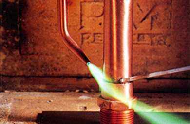
It’s hard to offer an exact (or even an in-exact) estimate of the number of factors that impact the life expectancy of a plasma cutter consumable —operator experience, type and age of the torch, material type and thickness, air quality, etc. However, when the operator understands good piercing and edge-starting techniques which keep molten metal from blowing back onto the torch nozzle (or tip if it is a non-Hypertherm system) then the life of the consumable can be extremely long. Hence, Hypertherm plasma cutter consumables have an edge over conventional plasma cutting machines.
Cutting Scenarios:
The biggest problem with most plasma cutter torches occurs when hand cutting with exposed (unshielded) nozzle-torch consumables. Ideally, you need to hold a standoff, with an unshielded setup at all amperages greater than 30 amps or so. If the nozzle touches the plate during a cut, it creates an electric current path between the negative electrode, nozzle, and positive plate. This causes a double arc between the electrode and nozzle, and the nozzle and plate, which damages the nozzle’s orifice. When the orifice gets a little damaged, poor angularity is the first thing you’ll notice, followed by more double arcs and more damage. Eventually, you’ll notice slower cut speeds and heavy dross, at which point you’ll likely change your nozzle.
Secondly, some people use a standoff device to hold the torch up off the metal. Unfortunately, molten metal can still blowback during piercing, once again passing electricity from the nozzle to the plate and leading to double arcing. If you have used a handheld torch with an exposed nozzle at more than 30 amps while drag cutting, you’ve likely felt the torch “sticking” to the plate. This is a result of double arcing.
Hypertherm Patented Solutions for Longer Life:
One way around this problem is through the use of shielded torch technology, invented and patented by Hypertherm in the ’80s. The shield works to electrically isolate the nozzle from the plate to totally eliminate double arcing. Hypertherm plasma shielded torches drag cut at up to 200 amps with no friction or double arcing for a dramatic improvement in a plasma cutter consumable’s life and cut quality.
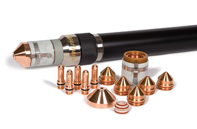
In the last 30 or so years since Hypertherm introduced shielded torch technology, engineers have made enormous strides in extending the life of these consumables. For example, our Duramax torches of Hypertherm plasma systems come with the new standard consumables with nearly all new Powermax systems and as a retrofit torch for older Hypertherm systems and use the shield for just nozzle isolation. The shield and nozzle for these torches use a patented technology called Conical Flow to inject greater airflow around the perimeter of the arc. This increases the energy density of the arc and provides better cooling to the nozzle. This results in no sticking, no double arcing, offering faster-cut speeds, thicker piercing capability, and dramatically longer nozzle life.
So, assuming you are using a Hypertherm plasma Duramax torch with the latest consumable technology, then I would expect you to cut hundreds of feet of metal. In addition, you should be able to make between 600 and 1,200 pieces, after which you would need to replace only your electrode. All your remaining Hypertherm consumables would likely continue to work just fine. Put another way, you should be able to get between 2 and 4 full days of actual arc-on time before needing to replace any of your consumables.
This is why Ador Fontech Limited, the name synonymous with total solutions for any Maintenance & Repair solutions, recommends Hypertherm plasma with Duramax Torch and consumables as a robust cutting solution to all our customers. “Using Spurious/Counterfeit consumables is nothing but a shortcut to machine breakdown & loss of warranty.”
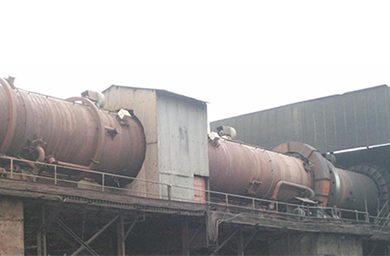
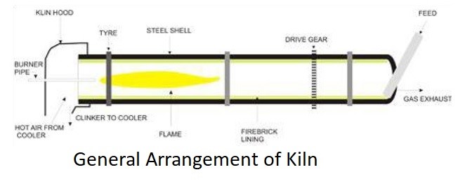
Cement Industry uses Rotary Kiln for Pyro-processing the raw mixture of finely crushed limestone (calcium carbonate + silica-bearing minerals) to manufacture cement. Kiln or kiln shell is at the heart of the cement-making process; its capacity, usually defines the capacity of the cement plant.
The Rotary Kiln consists of a tube made up of structural rolled steel material and lined with firebrick (or) castables. This kiln shell/tube slopes (1⁰to 4⁰) from one end to another, and slowly rotates on its axis at between 30 & 250 revolutions per hour depending on the plant. Raw mix is fed in the upper end and the rotation of the kiln causes the mix to move gradually to the other end of the kiln shell. At the other end to the lower part of the kiln, the burner pipe system provides a concentric flame. The raw mix moves under the flame and reaches its peak temperature before it drops out of the kiln into the cooler. In principle, the air drawn through the cooler flows into the kiln causing combustion of the fuel fed through burner pipe ensuring intense heat right across the kiln shell taking the temperature close to 1450⁰ C turning the raw mix into fully calcinated clinker.
This Kiln shell made of structural rolled steel has a tensile strength between 50,000 to 80,000 PSI at room temperature but once it goes beyond 200 degrees. The tensile strength drops rapidly and at around 430 degrees, studies have noted a strength loss of close to 50% from its original strength. Because of its continuous working condition at this high temperature along with corrosion caused by castables (which also cause thickness reduction in Rotary kiln or Kiln shell). After a period, fatigue develops in the kiln shell lining and with any small damage to the firebrick or castable it has a temperature attack or thermal shock in the kiln shell causing hot spots and red spots leading to cracks.
Hot Spot & Red Spot
Hot spot is an isolated area in the Rotary kiln where the Kiln shell temperature is close to 550 deg. It is not visible to to the naked eye but can be deducted by Shell scanner, also known as portable Infra-red pyrometer. Red spot is an area visible at night, indicating that the temperature is above 550 degrees. In layman’s terms, hot spot is like a warning sign that action is needed but red spot means immediate action with stoppage of Rotary kiln. Every hot spot eventually becomes a red spot-causing cracks in kiln shell. With today’s improved technology the shell temperature is monitored continuously with computer-aided sensors. At times kiln is stopped on deduction of a hot spot on further inspection cracks are noticed in the Kiln shell for immediate action
Generally, cracks that are perpendicular to rotary kiln and not of significant lengths and depth are repaired by welding. If the cracks are circumferential in nature, the particular portion is cut and removed & a new shell of the same length is inserted, aligned & welded. Also, kiln shell replacement is the preferred method in most cases of the red spot.
ADFL holds pre-eminence in both these types of repair – kiln shell repairs & kiln shell replacement. Further, we also offer a wear protection solution for high-temperature corrosion
We offer customized solutions for the repair of rotary kiln shell cracks with a combination of our LH 1105 & LH 521 alloys. We have credentials in attending a number of these kinds of breakdowns shutdowns
We are the only solution provider to offer automated kiln shell joining using the SAW process for kiln shell replacement jobs. By using an automated SAW process, we can complete a single joint in 24-36 hours – offering the highest productivity with X-ray quality welding
We also supply kiln shells & cowl shells of the required dimensions. This is a fabricated shell with single SAW joints, making it a value proposition to the industry.
We also have a Wear Protection solution for Rotary Kilns against high-temperature corrosion, Zircoat-M, a high-temperature coating, can be applied to a kiln shell’s inside portion before fixing castables to totally eliminate corrosion problems in kilns.
With such customized solutions for cement plant maintenance, repair, and refurbishment requirements, Ador Fontech Limited remains the first name to recall for customers across India, as we stay true to our motto of Life Enhancement of industrial components in every sphere possible.
To understand the types of Welding Electrodes, more commonly known as welding rods in welders parlance, it is essential to understand the particular type of application it is used for a specific industry. Welding is, primarily needed to fabricate new parts or components. Secondly, it is used to repair broken/cracked components or to hard-face and build up a worn-out component to prolong its life. Hence it is essential to classify welding by these two types of applications.
Electrodes for Fabrication Welding
Electrodes for Maintenance & Repair Welding
What is the Difference?
Specifications of welding electrodes (or) rods used in the production or fabrication of components are largely confined to meeting the minimum requirements of a particular class. Basically, conventional electrodes are designed essentially for production welding. In other words, they are expected to meet the specifications and design parameters of a specific component. Based on such an evaluation, a welding engineer chooses a particular electrode, only when it meets his requirements.
But in the case of Maintenance & Repair (M&R) welding, these specifications are too broad to realistically meet the precise & varied requirements of a repair application. Hence M&R products are basically Low Heat (LH) input welding rods or electrodes. They are designed to weld specific components to give them extended life or improve their performance. In most cases of M&R, we use a welding electrode to repair a broken component or worn-out component. In the process, we always go beyond the original design parameters to ensure that the refurbished component has the best properties & optimal performance.
Key Differences to Consider:
Composition of Base Material – In the case of fabrication welding, the job is carried out on new & known components, so all parameters are known. We can choose the welding material exactly, knowing the composition of the base material. This makes it easy to select the right welding electrode for the job. But in the case of Maintenance & Repair, the welding job is done without knowing the exact base material. This makes it necessary for us to have access to versatile products, which can be welded onto different types of base materials, like steel, cast iron etc.
State of Welding Component: In the case of fabrication welding, the job is done using pristine new plates. So, there are no special requirements while in the case of M&R welding, most of the welding needs to be done with fatigued, old, and contaminated components. Such welding jobs call for welding electrodes with richer chemistry & properties to match this specific requirement.
Preparation of Joint: In fabrication welding, all welding parameters are clear, so welders just need to adhere to them to complete a job properly. In the case of M&R welding, the job is many times conducted in-situ or at the site. This requirement complicates the task, as we will not be in a position to make any provision to prepare the area to be welded, like a V groove, which is ideal to ensure a proper job. Under such circumstances, the rich alloying elements of the welding electrode need to offer additional strength to the joint.
Type of Welding: Usually, any fabrication facility or workshop insists on executing a welding job using a flat or down-hand welding position only, as this is considered to be the best position to achieve ideal welding standards. But ensuring a down-hand welding position is not always possible with M&R welding because the work is mostly done on-site, and we may not always have the choice of position. This is why all M&R electrodes of Ador Fontech make are designed to enable welding from any position, making them unique.
Extended Work-Life: Extending the work-life of the original component is very important, in both types of welding as customers are more worried about the reliability and life extension offered by a repair. This is understandable as no plant can accept stoppages or breakdowns, especially after undertaking extensive repairs to fix all issues. M&R Electrodes/Rods offer an ideal solution in cases where we want to design products or components with extended life.
Special Re-Enforcement: When we are fabricating a component, it is always done as per a product’s design & drawing, so no special re-enforcement will be required. But in the case of M&R welding, we will be required to apply special re-enforcement techniques to ensure a long life for the repaired component.
Deadline for Completion: In fabrication welding, there is always a deadline set for completion, but it is always under control as this will be a planned activity. But most M&R welding jobs happen when there is a breakdown or stoppage. So, we need special products which can weld without pre or post-weld heat treatment so the job gets completed faster with the highest level of reliability.
Focusing on all the above considerations, Ador Fontech has designed & developed an exclusive Range of LH –Low heat Input Welding Electrodes/rods(Alloys) to resolve the specific problems in Maintenance & Repair welding.
Process industry generally requires the mineral ore’s needs to be processed. In other words, it needs to be crushed into a near powder form from its natural state. Typically, if you take an example from the cement industry, limestone extracted from mines is crushed close to a powder form before it moves on for further processing in grinding mills and then fed into a kiln from the cement-making process. The mines where the crushers are located form the backbone of the industry, making it a vital area for refurbishment as wear rates are very high due to high abrasion & impact caused by abrasive materials.
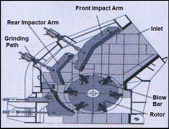
The most widely used and most efficient crusher machinery system for this task is the Hydraulic Impact Crusher. Nowadays this is predominantly used in Cement Industry as this simplifies crushing by doing the work of both primary & secondary crushers earlier used in the industry. The working process is very simple. Limestone ore is fed into the Horizontal Impact Crusher inlet as it falls into the rotating rotor. Then it gets crushed by the blow bar, inside the impact crusher during the crushing process, the front impact arm ensures the compressive loading of the ore. The rear impactor Arm & Grinding path ensures the fine crushing of limestone for further processing.
View of Horizontal Impact Crusher:
The main wear factors acting on the component are High Abrasion & Impact with compressive loading inside the Horizontal Impact Crusher. The main components get worn out are the front & rear impact arms or impactor arms, grinding path, blow bars, and the rotor body. So all these parts require a complete refurbishment to get the required profile to keep the crushing efficiency & also at the same time ensuring Life Enhancement of the worn-out components.
The best solution in the industry to give wear protection to all worn-out components is the unique single electrode solution developed by Ador Fontech LH TUFF-TECH 58 for high abrasion & high impact application. LH TUFF-TECH 58 is the ideal alloy for this application since its titanium carbide alloy system in martensitic matrix gives the best wear resistance to abrasion combined with impact outperforming all conventional hardfacing methodologies.
With this single titanium carbide alloy system LH TUFF-TECH 58, ADFL has replaced the conventional two electrode combination used as base layer & final layer. The most important aspect is that LH TUFF-TECH 58 outperforms all conventional Alloys with increased life by almost 40% as it gives superior wear resistance to this high abrasion & impact application.
The critical advantage with Ador Fontech is that the job can be executed at customer premises while complete refurbishment can be done at our Premises Life Enhancements services facility in Nagpur. Also, for greater customer convenience, this job can be executed through our authorized repair shops at locations close to the plant with trained manpower completely under our supervision.
The complete refurbishment of the horizontal impact crusher is a critical component highlighting the Ador Fontech way of life enhancement of industrial components. Our specially formulated wear solutions ensure Life Enhancement with maximum safety margin at a marginal cost of replacement giving the best value proposition to customers.
Four tough jobs made easier with Duramax Hyamp Long Torch
Skeleton removal
Scrapping
Structural demolition
Processing coils, test coupons, and castings
Additional benefits for all four jobs
Four tough jobs made easier with Duramax Hyamp Long Torch
We all know that processing metal can be a hard job. It’s hot, dirty, and then there are the physical demands it can put on your body. Metal is heavy, and depending on the size of the plate, difficult to move. It becomes even harder to maneuver when the metal is welded into a sub-assembly or final product. Then to further complicate matters, there are staff shortages, safety concerns, cost constraints, and of course, deadlines to meet.
What if there was a better way to do some jobs? Hypertherm created the Duramax Hyamp Long torch with exactly that aim in mind. Jing Wu, Hypertherm’s lead engineer on this project explains, “We want to help our customers and keep them safe.” Wu and his team based the new handheld torch’s design on what operators told them, and what they themselves observed in shops, yards, and plants. It was clear that “extended reach” is beneficial for several reasons, and by offering longer torch-body lengths, existing Hypertherm – Powermax owners could expand their range of applications.
Here are four jobs that get immediately improved by adding the Duramax Hyamp Long torch to your Hypertherm Cutting System.
1. Skeleton removal
If you’re using oxyacetylene to cut and remove skeletons from your table bed, it’s slowing down your production line. Undoubtedly, Hypertherm Plasma Cutting is faster than oxyfuel but by switching to the Duramax Hyamp Long torch, you can do the same job in a third to a quarter of the time. Existing long torch customers report skeleton removal from heavy industrial CNC beds is so fast, that jobs previously taking an hour, now can be finished in less than 15 to 20 minutes. The savings add up fast.
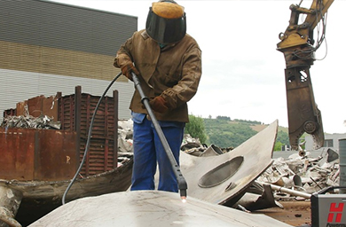
2. Scrapping
Every scrapper will benefit from having a long torch in their yard. Not only can plasma cut steel, stainless, and aluminum, it cut exotic metals, like copper and brass, and alloys too. The portability of Hypertherm Powermax plasma systems like Powermax 45 & Powermax 65 makes it possible to demolish large-scale depreciated machinery out in the yard, allowing for larger, more lucrative trades with mills. The Duramax Hyamp Long torch is also better than a shear at making long cuts. Plus, it frees up shears to cut the smaller pieces into dimensions required by steel mills, thus making the shear more productive as well.
3. Structural demolition
Structural steel companies tearing down buildings and other facilities, like decommissioned nuclear plants or sports stadiums, use multiple long torches to speed up the job. Completing the job faster saves on labor costs, but it helps them earn their contractual performance incentives too. Hence this Long torch solution connected with Hypertherm Power Systems is most ideal for such jobs.
4. Processing coils, test coupons, and castings
Mills manufacturing steel and other metals are hot places. Furnace’s heat, melt and liquefy raw ore and recycled scrap metal to form new rolled and cast metal products. As noted above, the long torch creates more distance and allows operators to stand further away from the radiant heat, translating to less fatigue and more productivity to customers underlining the benefits of Hypertherm Plasma Systems.
Additional benefits for all four jobs
The Hypertherm Plasma with Duramax Hyamp Long torch is safer to use. It’s ergonomic, allowing operators to work from comfortable positions. The length of the torch body and the angle of the cutting head lets operators stand upright, while still gaining the accessibility they need. Operators avoid back pain that results from having to bend over repeatedly to ignite the flame torch with a striker and operators can stand beside CNC tables, rather than on top of the cutting bed.
This is why Ador Fontech Limited, the name synonymous with total solutions for any Maintenance & Repair solutions offers Hypertherm Duramax Hyamp Long torch as a Robust Cutting solution to our customers.


 2. Scrapping